Statement 1: A resistor limits or controls the flow of electric current in a circuit.
Statement 2: In an LED, the longer leg is the negative (cathode) terminal.
Statement 3: A capacitor stores electrical charge and is often described as a "bucket of charge".
Statement 4: A diode allows current to flow in both directions (forward and reverse).
Statement 5: According to Ohm's Law, voltage equals current multiplied by resistance (V = I × R).
Statement 6: A potentiometer can function as a voltage divider.
Statement 7: VCC typically refers to the supply voltage (positive voltage supply).
Statement 8: GND means "general neutral level".
Statement 9: There are several different types of capacitors.
Statement 10: A capacitor may explode if it is connected incorrectly (wrong polarity).
Statement 11: If a circuit has too small a resistance, the wires may melt.
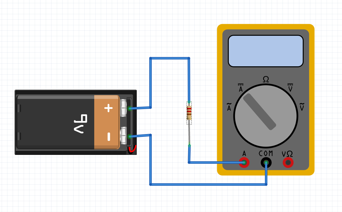
Statement 12: When measuring current with a multimeter, you must check that the meter's maximum current limit is not exceeded.
Statement 13: Resistance can be measured using the voltage setting on a multimeter.
Statement 14: A transistor can act as a switch.
Statement 15: AC stands for Alternating Current.
Statement 16: DC stands for Direct Current.
Statement 17: A battery typically provides DC voltage.
Statement 18: A silicon diode typically has a forward voltage drop of about 0.7 V.
Statement 19: A transistor has three terminals.
Statement 20: A voltage divider circuit uses two resistors.
Statement 21: If a battery is marked 9V, it means it can supply 9 amperes of current.
Statement 22: There are two main types of transistors: current-controlled and voltage-controlled.
Statement 23: A transistor can control high power with very small power.
Statement 24: Capacitance describes the properties of a transistor.
Statement 25: In a battery, current flows from lower voltage to higher voltage.
Statement 26: When a circuit is closed, part of the current flows outside the circuit.
Statement 27: A fuse is designed to protect an electrical circuit.
Statement 28: The value of a fuse is typically specified in Amperes.
Statement 29: In household use, 10W is a typical power rating for an LED lamp.
Statement 30: In a car, a lamp marked 12V and 1A consumes 12W of power.